Truth Table
You can generate a truth table for your subcircuit if it has input and output pins and doesn’t include memory elements like flip-flops or RAM. In other words, your circuit must behave like a pure function.
Learn more about pure functions: Pure Function (Wikipedia)
Learn more about truth tables: Truth Table (Wikipedia)
To create a truth table, go to the menu: Circuit/Truth Table.
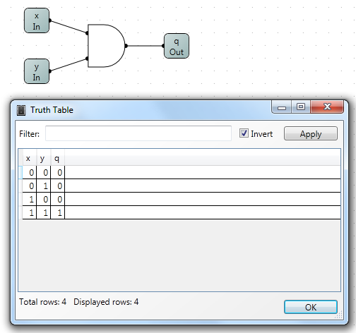
The dialog will show a table with columns labeled by the input and output pin names. Each row shows a combination of input values and the corresponding output.
Here’s another example using a full adder:
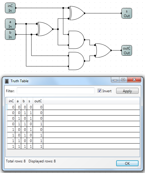
The number of rows in a truth table equals 2 raised to the total number of input bits. For example, with 3 one-bit inputs, the table will have 23 = 8 rows. Adding more input bits increases the size of the table quickly. However, the dialog will only show up to 4096 rows for usability.
Filtering Rows
You can use a filter expression to display only certain rows. Filters use pin names and logical conditions.
For example, for an AND gate, the filter q = x & y checks that output q matches the expected result.
There’s a checkbox to invert the filter. When checked, only the rows that don’t match the condition will appear. This is useful for debugging.
At the bottom of the dialog, you’ll see two numbers: total rows and the number currently displayed.
Expression Syntax
To use pin names in expressions:
- If the name starts with a letter and contains only letters and numbers (e.g.,
x1,Pin3), just use the name directly. - If the name contains special characters, spaces, or starts with a digit, put it in double quotes (e.g.,
"1a","out pin"). - Escape quotes or backslashes in names using a backslash:
"a\"","a\\pin".
You can write numbers in different formats:
- Decimal:
0,10 - Hexadecimal:
0x1A,0XFF - Octal:
012,077 - Binary:
0b101,0B0011
_ or ' in numbers for readability, e.g., 0b1010_0001.
Operations in Expressions
There are two types of operations:
- Arithmetic – Performs calculations like addition or bitwise shifts.
- Logical – Evaluates to 1 (true) or 0 (false), such as comparisons or logical AND.
Examples:
3 + 4results in7(arithmetic)3 < 5results in1(logical)
Some supported operators:
| Priority | Operator | Description |
|---|---|---|
| 1 | (E) | Parentheses |
| 1 | -E, ~E, !E | Negation, Bitwise NOT, Logical NOT |
| 2 | <<, >> | Bitwise Shifts |
| 3 | & | Bitwise AND |
| 4 | |, ^ | Bitwise OR, XOR |
| 5 | *, /, % | Multiply, Divide, Modulus |
| 6 | +, - | Add, Subtract |
| 7 | =, ==, !=, <>, <, <=, >, >= | Comparisons |
| 8 | && | Logical AND |
| 9 | || | Logical OR |
For example, if you're checking only the sum bit s of a full adder, you may need to mask the carry:
s = (inC + a + b) & 1
Using Functions
You can define reusable functions like this:
function_name(arg1, arg2, ...) : expression
Example: Check if a number is even:
is_even(n) : (n & 1) = 0
Use it in an expression like:
is_even(a + b) && is_even(c)
Another example using a multiplexer:
case(n, e) : (N = n) * e
case(0, X0) + case(1, X1) + case(2, X2) + case(3, X3) = Q
Make sure function names and their parameters don’t match any circuit pin names.
It is also possible to define a function without parameters. In such case just specify function name, colon, and expression for this function To call it just type its name. For example:
B:(b ^ (Nb * 0xF)) a + B = q && c + B = q
Where: B:(b ^ (Nb * 0xF)) is function definition and a + B = q && c + B = q is use of function B.