Building advanced circuits
Creating sub circuits
In order to build more advanced circuits you need to create reusable logical circuits.
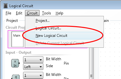
To create it click menu Circuit/New Logical Circuit.
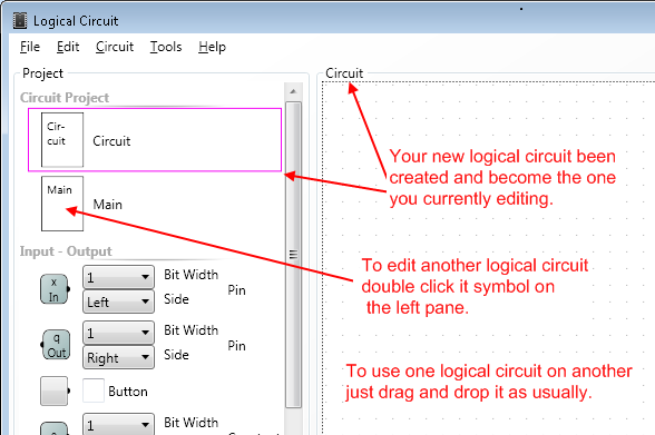
To switch between your circuits you can double click them on the left panel or pressing Ctrl + Tab or Ctrl + Shift + Tab to navigate through circuits in reverse historical order. Press Tab more than once while holding Ctrl to navigate further in the history.
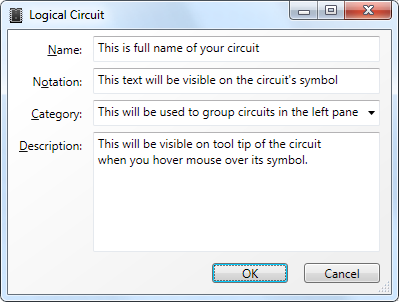
After you've created a new logical circuit you want to rename it and change text on its symbol.
To change properties of current logical circuit double click anywhere on the design surface, but not on any symbol. The circuit properties dialog will pop up. You also can open the same dialog by clicking menu Circuit/Logical Circuit.
Note that most of dialogs are resizable so make sure you see all the controls on the dialog.
Input and output pins
After you've created a new circuit it does not have any pins on its symbol's edges.
In order to wire it to other circuits you should define its input and output pins. This is very simple; just drag and drop as many input and output pins on the design surface of your circuit.
By default all input pins goes to the left side of the circuit symbol and output ones to the right side.
To change properties of the pin just double click it on the design surface and pin dialog will pop up.
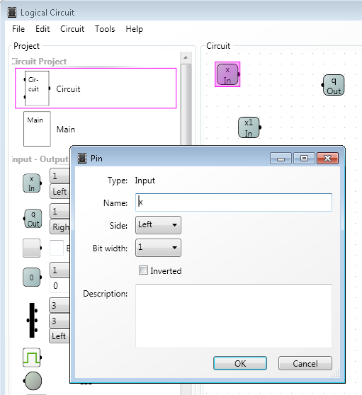
You can change name, description, side of the circuit symbol where the pin will reside, give a description of the pin that will be visible when you hover mouse over it and provide its bit width. For more details on multi bit pins read about splitter.
To change the position of the pin on the side of the circuit's symbol you can move it on design surface relatively to other pins that reside on the same side. So if pin lower on the design surface it will be lower on the symbol's side if it on the right of the other pin it will be lower or righter on the symbol and so on.
The fact the pin is input or output is used to put input pins to the left and output pins to the right edge of circuit by default. It is also used to build truth table. However all pins are bidirectional, that means you can use either of them for both input and output signal. You can just think of them as piece of copper connecting inside of the circuit to its outside.