LED Matrix
To learn more about LEDs – Light-Emitting Diodes please read the following Wikipedia article:
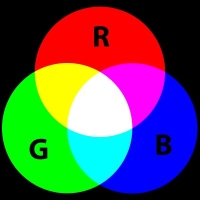
http://en.wikipedia.org/wiki/Light-emitting_diodeLED Matrix is a grid of LED’s cells. Each cell contains up to 3 LEDs of red, green and blue colors. Color of each cell is a combination of colors of lit diodes:
For more on RGB color model please read:
http://en.wikipedia.org/wiki/RgbEach matrix can contain up to 10 rows and 10 columns. Each cell can be of rectangular or round shape.
There are two ways of controlling the matrix:
- By controlling each individual LED.
- By controlling all LEDs on intersection of selected columns and rows.
The difference is in the bit width and number of input pins on the matrix.
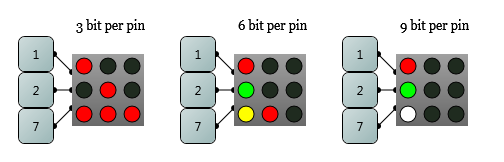
For the first type of the matrix the left edge will contain as many pins as many rows is in the matrix and bit width of each pin will be equal to the number of column in the matrix multiplied by the number of colors in each dot. For example the following three matrices have 3, 6, and 9 bit width of each pin.
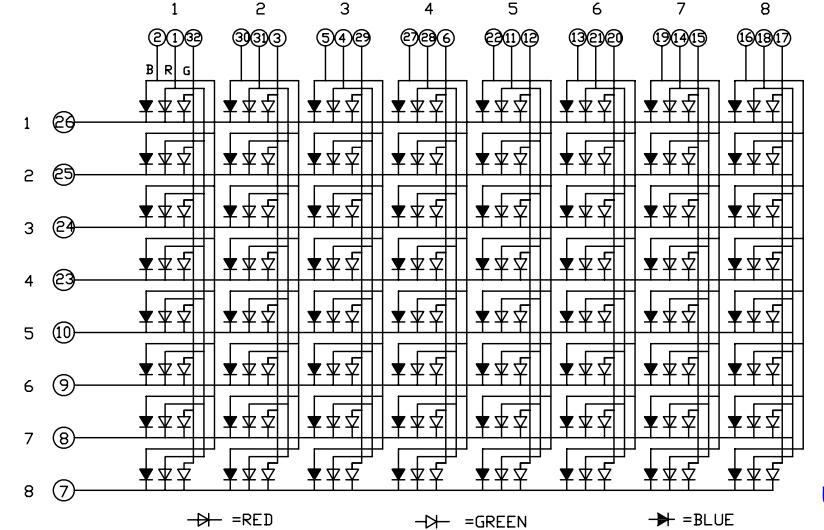
The second type of matrix is somewhat more real. The matrices available on the market are controlled in the same manner. It has pins in the left and top edges of the matrix. There are as many pins on the left edge as many rows on the matrix; there are as many pins on the top edge as many columns on the matrix. Pins on the left edge are all 1 bit wide, while widths of the top pins on are equal to number of colors of each cell. The real matrices are controlled like this because LEDs are wired like on this circuit:
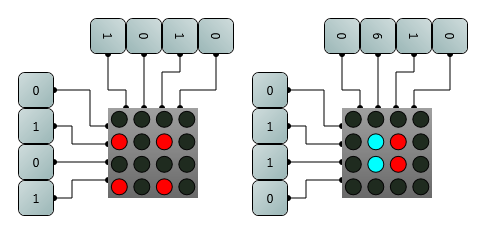
The cell in the matrix will be lit if the correspondent pins on the left and top edges are set to non-zero state. See these two examples.
To control such matrices usually you need to build a special driver that will select one row at a time and set state of all columns to what is needed for this row. In the next cycle the driver will select next row and lit all required cells and so on. So at each particular moment only one row is lit and if you roll rows fast enough the eye will not notice the dynamics but will see a formed picture instead. In Logic Circuit program however it will artificially lit for a little bit longer after the cell turned off in order to simulate this effect.